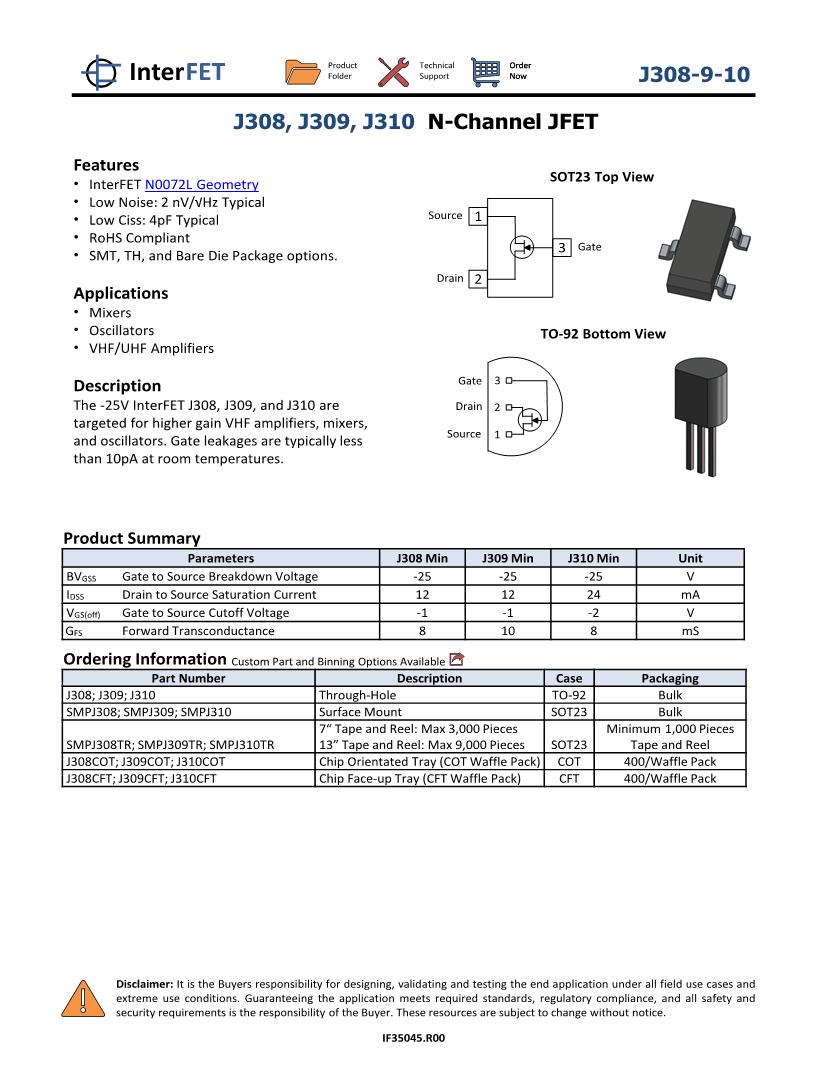
Electronic ManufacturerPart NumberDatasheetElectronics Description
- JFET JFETs are available at Mouser Electronics from industry leading manufacturers. Mouser is an authorized distributor for many JFET manufacturers including Fairchild, ON Semiconductor, Vishay, & more. Please view our large selection of JFETs below.
- 3.1 JFET Gate-To-Source Voltage Variation. In the previous section, we developed the i-v.
- Junction field-effect transistor, or JFET, is perhaps the simplest transistor available. It has some important characteristics, notably a very high input resistance. Unfortunately, however (for the JFET), the MOSFET has an even higher input resistance.
- During this region, the JFET is On and active. Breakdown Region- This is the region where the voltage, VDD that is supplied to the drain of the transistor exceeds the necessary maximum. At this point, the JFET loses its ability to resist current because too much voltage is applied across its drain-source terminals.
Junction Field Effect Transistor: A junction field effect transistor (JFET) is the the simplest type of three-terminal semiconductor transistor. JFETs are widely employed as electronically controlled switches, voltage-controlled resistors and amplifiers. The semiconductor material in a JFET is positively and negatively doped and arranged to.
ON SemiconductorTF410-TL-HN-ChannelJFET40V, 50 to 130A,0.11mS,USFPNew Jersey Semi-Conduct...2N3684N-CHANNELJFETLOWNOISEAMPLIFIER
Micross ComponentsPN5115_TO-92P-CHANNELJFETLS844_TO-71MONOLITHICDUALN-CHANNELJFET2N4416A_TO-92a N-ChannelhighfrequencyJFETamplifier
Linear Integrated Syste...LSK170ULTRALOWNOISESINGLEN-CHANNELJFET
Vishay Siliconix2N5564
 MatchedN-ChannelJFETPairs
ON Semiconductor2N5555JFETSwitching
 NSVJ3910SB3_16
 N-ChannelJFET
Unisonic TechnologiesK1109_15N-CHANNELJFETFORELECTRETCONDENSERMICROPHONE
New Jersey Semi-Conduct...SST4391SINGLEN-CHANNELJFETSWITCH
How To Bias N Channel Jfet
2N4091N-CHANNELJFETSWITCHMicross ComponentsSST109_SOT-23N-CHANNELJFETLS845_SOICMONOLITHICDUALN-CHANNELJFETLS832_SOT-23MONOLITHICDUALN-CHANNELJFETLS4118A_TO-71Ultra-HighInputImpedanceN-ChannelJFET
Seme LAB2N4393C1SILICONSMALLSIGNALN-CHANNELJFET
Intersil CorporationU1897N-ChannelJFET
Jfet Vs Mosfet
SwitchLinear TechnologyLT1464
 Dual/QuadMicropower,1MHzC-LoadPicoampereBiasCurrentJFET
J Fetzer Pottery
Input Op Amps
NTE ElectronicsNTE861IntegratedCircuitQuad,NormallyOpen,SPSTJFETAnalogSwitchw/Disable
JFET vs MOSFET vs MESFET-Difference between JFET MOSFET and MESFET
This page compares JFET vs MOSFET vs MESFET and describes difference between JFET, MOSFET and MESFET.The other useful links to difference between various terms are provided here.
JFET
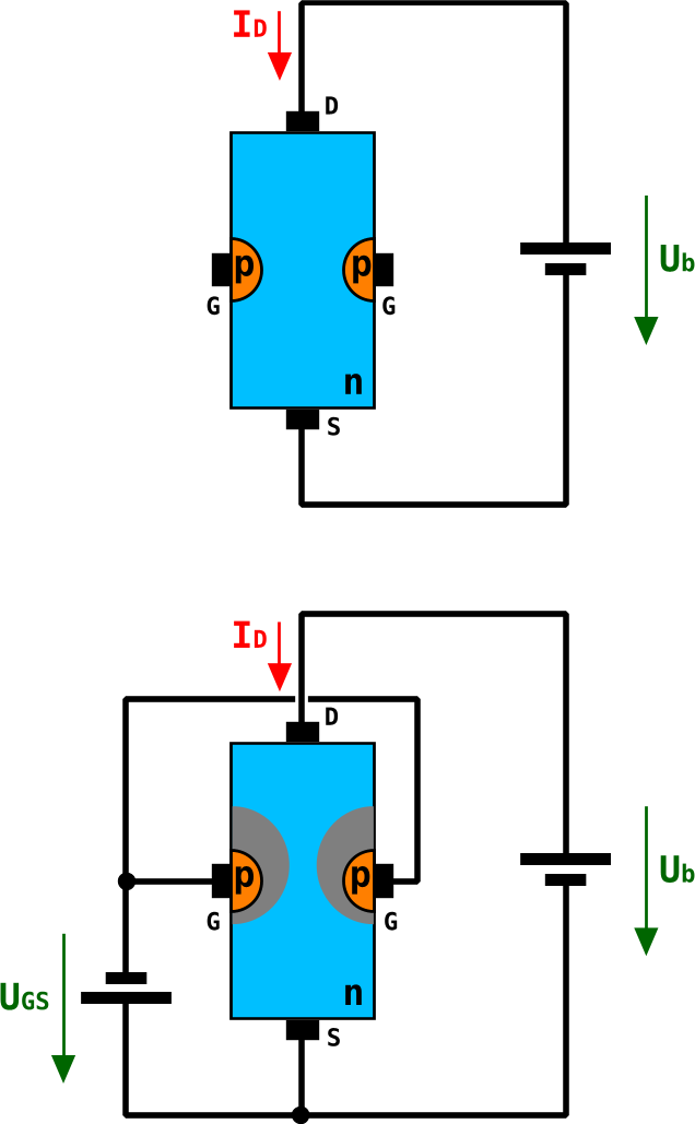
The figure-1 depicts internal structure of the JFET device.Following are the features of JFET:
• The gate voltage controls the channel conductance by modulating the width of the depletion region at the p-n junction.
• The p-region doping is MUCH higher than in the n-region. The depletion region expands mostly into the n-channel.
• For the p-channel JFET, the n-type layer will be doped higher than the p-channel.
MOSFET
The figure-2 depicts internal structure of the MOSFET device.Following are the features of MOSFET:
• Gate control through a MOS barrier
• The device in normally-off and current only flows when the gate bias inverts the channel
• Both p-channel and n-channel MOSFETs are possible giving rise to CMOS
• MOSFETs typically will have cutoff frequencies less than 1 GHz.
• Main Application: Integrated circuits, microwave operation is not yet possible
MESFET
The figure-3 depicts internal structure of the MESFET device.Following are the features of MESFET:
• Gate control through a Schottky barrier
• The device in normally-on and negative gate-bias is needed to cut the current off (in case of the n-channel MESFET)
• Typically n-channel MESFETs are feasible
• MOSFETs typically will have cutoff frequencies greater than 10 GHz.
• Main Application: Microwave devices, integration not as high as the CMOS devices
RELATED LINKS
BJT vs FET
Diac vs Triac
JUGFET vs MOSFET
Photo Diode vs Photo Transistor
SCR or thyristor
Op-Amp
Halfwave rectifier vs Fullwave rectifier
What is Difference between
difference between FDM and OFDM
Difference between SC-FDMA and OFDM
Difference between SISO and MIMO
Difference between TDD and FDD
Difference between 802.11 standards viz.11-a,11-b,11-g and 11-n
OFDM vs OFDMA
CDMA vs GSM
Bluetooth vs zigbee
Fixed wimax vs mobile
RF and Wireless Terminologies
J Fetzer
Share this page
J Fetzer Pottery Ohio
Translate this page
